Services > Assemblies > Grab Sampling Program
Grab Sampling Program
We offer grab sampling consulting and fully built grab sample panels. Please explore options below, download details, and get in touch. Tel: 780-437-0640.
.png?width=400&height=300&name=Grab%20Sampling%20Systems%20Application%20Guide%20(400).png)
Swagelok Grab Sampling Systems Application Guide
Comprehensive Grab Sampling Solutions
Many plants our Swagelok Field Advisors visit lack a proper grab sample system. It doesn't have to be that way. Our Grab Sampling Program is designed to ensure every grab sample is representative. So you can validate process conditions, product quality, emissions compliance, and more.
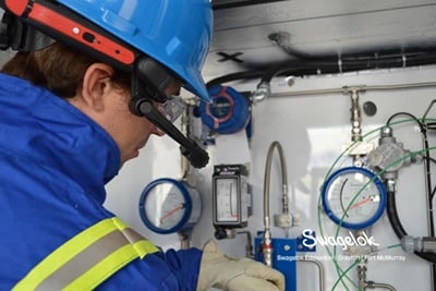
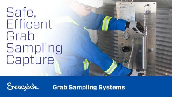
We offer Field Advisors specially trained to evaluate how samples are captured, handled, and analyzed. They are available to examine your systems and specify a safe, reliable grab sampling system. Our Custom Solutions Team builds assemblies in our Edmonton shop, configuring each panel to your needs. Easy to install and operate, our system delivers the quality you expect from Swagelok.
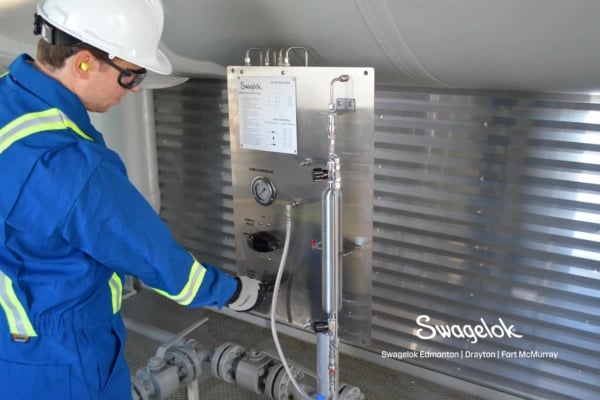
Photo: Swagelok Edmonton Field Advisor Tom Webster has completed years of training under the some of the world's leading authorities on industrial sampling systems.
Standard Grab Sample Panel Designs
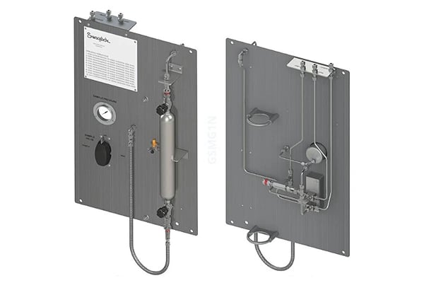
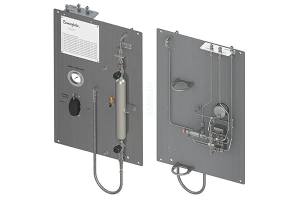
Standard Gas Sampler Without Purge
Swagelok's Standard Gas Sampler is for general use for gas sampling. It is recommended for non-toxic gases and systems when the return is sent to flare. See the Grab Sampling Systems Application Guide for details.
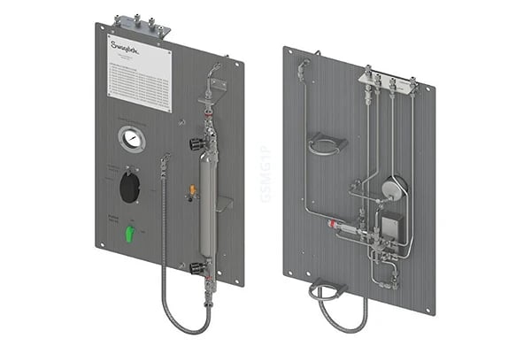
Standard Gas Sampler with Purge
The Standard Gas Sampler With Purge is for general use for liquid sampling. Its purge option (using gas or a solvent) clears fluid before and/or after sample collection. It is recommended for gases that are toxic or with condensable hydrocarbons and systems when the return is sent to flare. See the Grab Sampling Systems Application Guide for details.
Continuous Flow Gas Sampler Without Purge
Swagelok's Continuous Flow Gas Sampler Without Purge is for general use for gas sampling. It is Recommended for gases that are non-toxic gases and for samplers installed directly in the sample stream, on a fast loop; and where long sample transport lines are used. See the Grab Sampling Systems Application Guide for details.
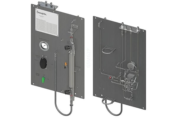
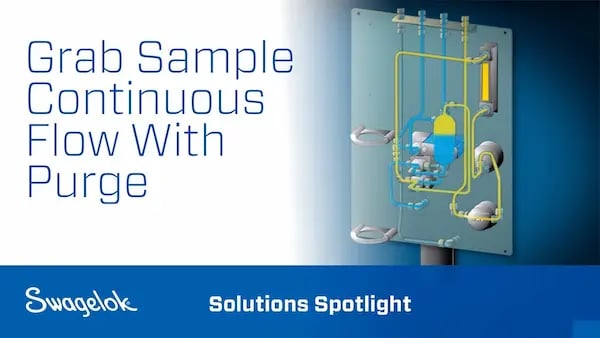
Continuous Flow Gas Sampler with Purge
This panel design is intended for general use for gas sampling when continuous flow is required from inlet to outlet. The purge option clears sample fluid from the sample transport lines before and/or after sample collection. It is recommended for gases that are toxic or with condensable hydrocarbons and in cases where samplers are installed directly in the sample stream, on a fast loop, or where long sample transport lines are used. See the Grab Sampling Systems Application Guide for details.
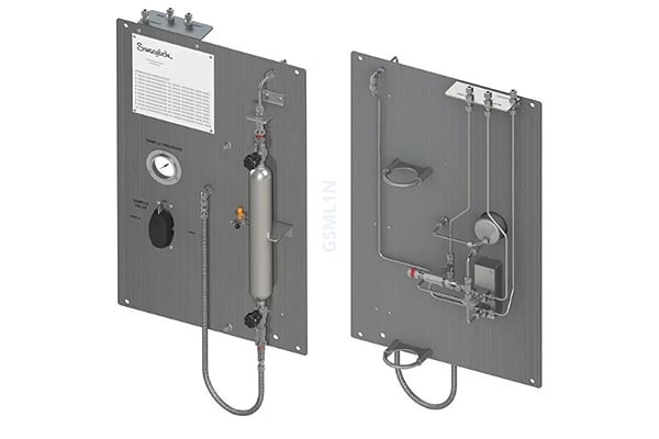
Standard Liquid Sampler Without Purge
Swagelok's Standard Liquid Sampler with Purge is for general use for liquid sampling. The purge option (using gas or a solvent) clears fluid before and/or after sample collection. It is recommended for fluids that are toxic or may settle in the sampler, and for when the return is sent to flare. See the Grab Sampling Systems Application Guide for details.
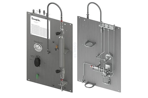
Standard Liquid Sampler with Purge
Swagelok's Standard Liquid Sampler with Purge is for general use for liquid sampling. The purge option (using gas or a solvent) clears fluid before and/or after sample collection. It is recommended for fluids that are toxic or may settle in the sampler, and for when the return is sent to flare. See the Grab Sampling Systems Application Guide for details.
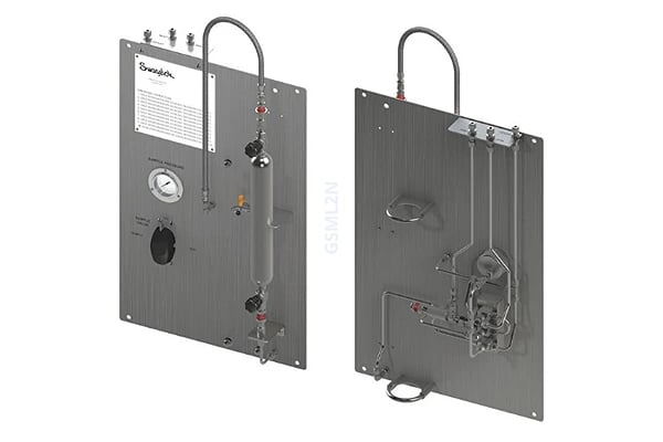
Continuous Flow Liquid Sampler Without Purge
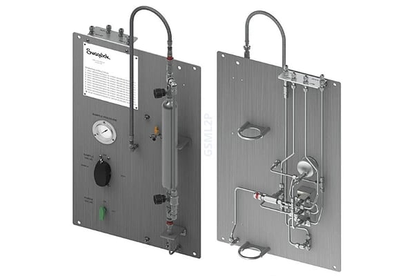
Continuous Flow Liquid Sampler with Purge
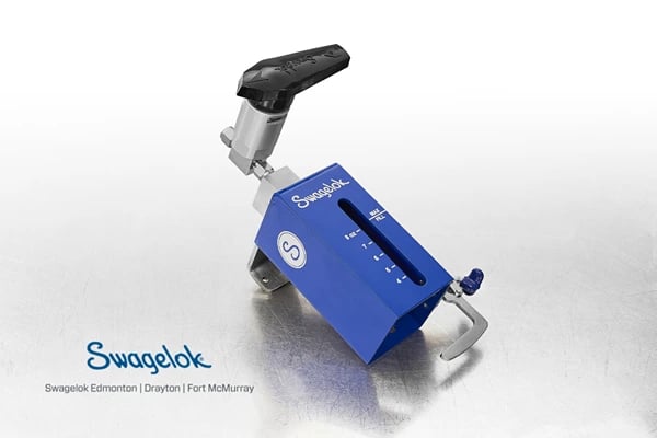
Simple Liquid Sampler
Swagelok's Simple Liquid Sampler is for general use for liquid sampling. Recommended for non-toxic liquids. See the Swagelok Grab Sampling Systems Application Guide for images and details.

Simple Liquid Sampler with Purge

Continuous Flow Liquid Sampler

Continuous Flow with Purge

Liquid Sampler with Back Purge

Liquid Sampler with Fixed Volume

Liquid Sampler with Fixed Volume and Continuous Flow
Onsite Integration Support
We can come onsite at installation to personally answer any questions from installers, operators, technicians, and managers. While your expert is on hand, practice operation, discuss maintenance, and fine-tune your panel(s). Our goal is seamless integration with your existing fluid systems, operations, and team.
Process
Evaluation
Specification
Solution

Grab Sampling Program iPDF
Specifying a Swagelok Grab Sampling System
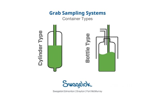
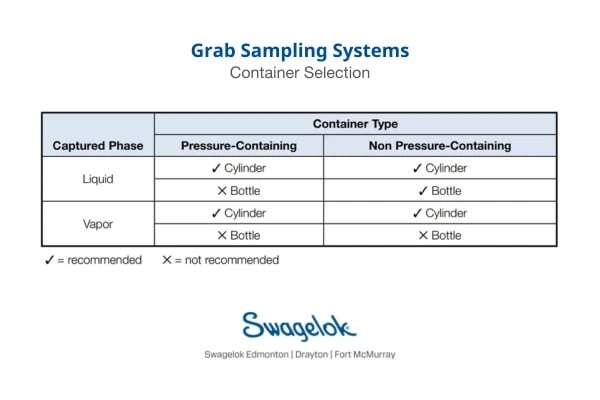
Two system types allow for capture into one of two types of containers: pressure‑containing metal cylinders as found in the Grab Sample Module (GSM) or non-pressure‑containing glass or polyethylene bottles as found in the Liquid Only Sampling Module (GSL).
Container Type
Sample Cylinder – the GSM system is for samples with a vapor pressure above 14.7 PSIa (1.01 Bara) at ambient conditions. The GSM uses pressure-rated sample cylinders which prevent the sample from escaping, even under pressure, and are durable to prevent accidental breakage. The GSM is the most reliable method of capturing a sample.
Bottle Sampling – the GSL system is for samples with a maximum vapor pressure of 14.7 PSIa (1.01 Bara) at ambient conditions. The design allows for the use of less expensive glass laboratory bottles to draw and store the sample. Using bottles also provides immediate feedback on the visual quality of the sample stream.
Collaboration
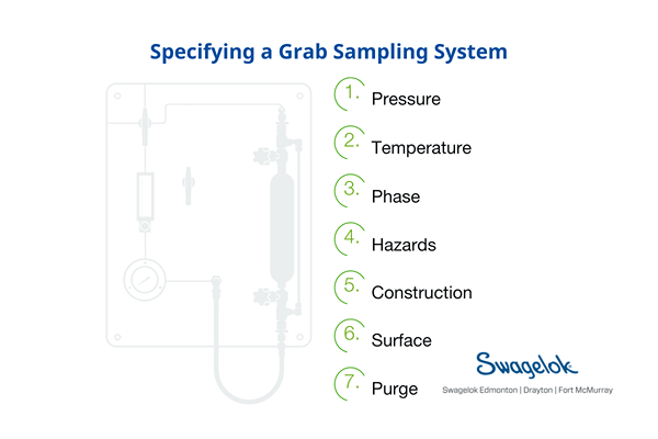
Ensuring your grab sampling system is suitable for your particular purpose is key. Temperature, pressure, phase, container type, materials of construction, and where the panel will be installed are just a few of the criteria to consider in order to properly specify a grab sampling system.
Our team takes you through a checklist of details to ensure the panel we recommend will meet your system needs. The product selection matrix (below on this page) provides some common system criteria that may help you with the decision making process. Next, a certified expert will review your information and recommend a panel per your requirements.
Specification
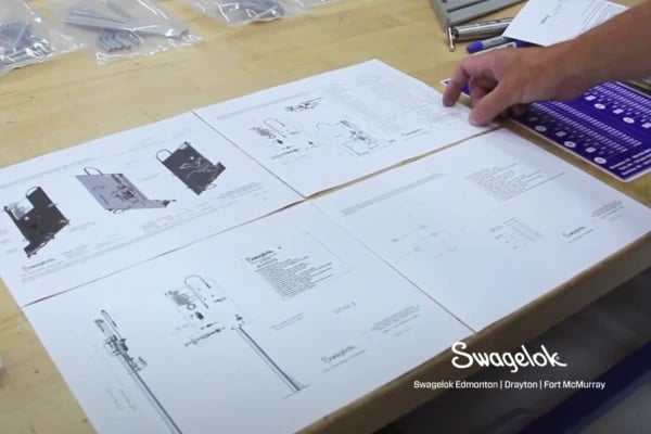
Using our standard panel designs as a platform, we can work with your team to substitute comparable Swagelok and non-Swagelok products if necessary; add products within the existing schematics – sample coolers, flow meters, shut-off valves, drain valves, etc; and make changes in the layout.
If needed we can make structural changes/additions—panel/bracket materials, enclosures, etc.; convert to larger/smaller tube size (or metric); and recommend alternate materials of construction. Likewise, we can make flow/pressure drop calculations (and make changes based on results) and/or recommend sizing of sample coolers/heaters and enclosure heaters (using vendors’ applications engineering).
.webp?width=300&height=162&name=Collection%20-%20Grab%20Sampling(300).webp)
Swagelok Grab Sampling Best Practices Technical Briefing
In-House Design, Assembly, and Testing
Our team of certified fluid system designers and assembly technicians build your solution in our Edmonton, Alberta shop.
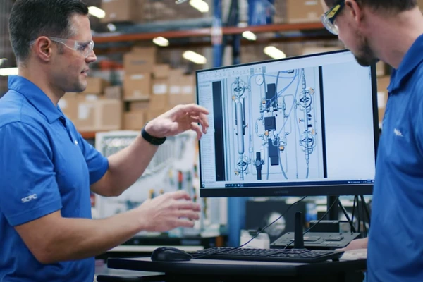
Certified Assembly Technicians
Every technician has undergone a comprehensive training and certification program—repeated every three years—to ensure every assembly meets strict guidelines. Our certified Engineer monitors each step to ensure quality and consistency.
.jpg)
Every Unit Shell Tested
Every GSM and GSL is shell tested at the selected gauge pressure of the assembly, up to a maximum of 1000 psig (69 bar). Additional testing is available on request. Your assemblies are backed by Swagelok's industry-leading warranty.
.webp)
Onsite Integration Support
Our goal is seamless integration with existing systems and operations. We are onsite to help with final adjustments, demonstrate operation, discuss maintenance, and answer questions from installers, operators, technicians, and managers.
.png?width=400&height=300&name=Assembly%20_%20Grab%20Sampling%20Program%20Infographic%20(2).png)
Swagelok Edmonton Infographic & Reviews
Swagelok Grab Sampling Advantage
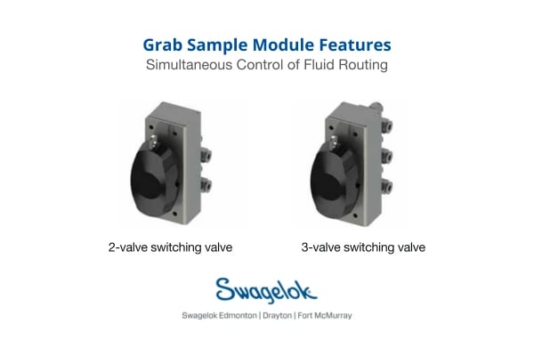
Simultaneous control of fluid routing
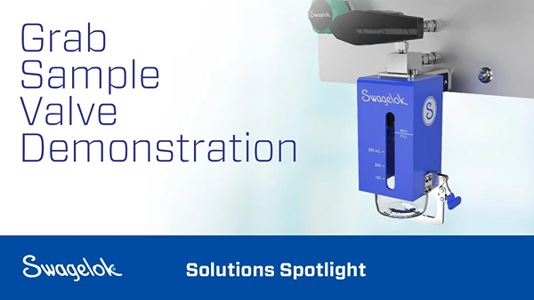
A key feature of the GSM is the switching valve that directs flow. Using the Swagelok 40G series ball valve for this switching valve, configurations are available with either 2 or 3 valves.
Simultaneous control of fluid routing means fewer steps required to draw a sample. The likelihood of errant sampling is reduced and a clear indication of sequencing is provided to the operator. This valve assembly is a standard on all GSM panels as well as fixed volume GSL panels.
Closed-loop system
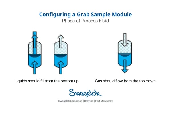
The closed-loop sampling system pulls from a positive-pressure process and returns back to the process at a lower pressure location (e.g., upstream of a pump), using the differential pressure to drive the fluid through the sample system. This circuit draws a flow path that connects to the sampler then returns to the process or to flare.
With some arrangements a GSM can be left in the bypass or sample position indefinitely, keeping the transport lines fresh (with zero flushing time) and ready for sample capture. A rupture disc is an available option for every GSM system. A relief valve can also be added to the sampling systems.
Liquid sampling using glass
The GSL design allows for the use of less expensive glass laboratory bottles to draw and store the sample. Using bottles also provides immediate feedback on the visual quality of the sample stream. Swagelok GSL systems use the same switching valve as a GSM system to provide simplified operation for complex tasks. The GSL systems also include Sentry Equipment’s Model MVS to draw a sample into a bottle.
10 Sampling System Mistakes Whitepaper
Product Selection Matrix
The table below provides a summary of common system criteria and the grab sample system recommended for the listed combinations. The page numbers refer to the Swagelok Grab Sampling Systems Applications Guide (available for download at the top of this page).
| GRAB SAMPLE SYSTEM PRODUCT SELECTION MATRIX | ||||||||
| Pressurized Storage | Sample Receiver | Sample Phase | Continuous Flow | Purge | Fixed Volume | Back Purge | Ordering Number | Reference Page No. |
| Yes | Cylinder | Liquid | No | No | Yes | No | GSM-L-1(-N) | 9 |
| Yes | Cylinder | Liquid | No | Yes | Yes | No | GSM-L-1(-P) | 10 |
| Yes | Cylinder | Liquid | Yes | No | Yes | No | GSM-L-2(-N) | 13 |
| Yes | Cylinder | Liquid | Yes | Yes | No | No | GSM-L-2(-P) | 14 |
| Yes | Cylinder | Gas | No | No | No | No | GSM-G-1(-N) | 11 |
| Yes | Cylinder | Gas | No | Yes | No | No | GSM-G-1(-P) | 13 |
| Yes | Cylinder | Gas | Yes | No | No | No | GSM-G-2(-N) | 15 |
| Yes | Cylinder | Gas | Yes | Yes | No | No | GSM-G-2(-P) | 16 |
| No | Bottle | Liquid | No | No | No | No | GSL1 | 29 |
| No | Bottle | Liquid | No | Yes | No | No | GSL2 | 30 |
| No | Bottle | Liquid | Yes | No | No | No | GSL3 | 31 |
| No | Bottle | Liquid | Yes | Yes | No | No | GSL4 | 32 |
| No | Bottle | Liquid | No | Yes | No | Yes | GSL5 | 33 |
| No | Bottle | Liquid | No | No | Yes | No | GSL6 | 34 |
| No | Bottle | Liquid | Yes | No | Yes | No | GSL7 | 35 |


