 From start to finish, fugitive emissions are a stumbling block for a refinery. Inefficient at best and hazardous at worst, facilities need to provide a clear outline to operators on how to correct these leaks when they arise. At the heart of any successful campaign is leak detection and repair, known shorthand as LDAR.
LDAR aims to catch and alleviate current leaks, but also expand its scope to monitor when and why leaks may be occurring. To best understand how to curb fugitive emissions of a refinery, the flow of the LDAR system is key. Additionally, with a general overview of LDAR functions, the system can be better adjusted to the needs of its users. With a proper LDAR system implemented, the focus can turn to some of the more notorious elements for fugitive emissions in a fluid system and how best to maximize their functionality while minimizing the occurrence of fugitive emissions.
When discussing LDAR, it’s important to note that the issue of leaks is not as simple as a search and rectification; LDAR is an iterative process of remedying active leaks while preventing future emission events. Here’s a look at what an LDAR system may broadly entail:
To help make the logistics of tracking thousands of possible emission points easier, each component should be provided with a unique identifier. All relevant documentation, and especially diagrams indicating the physical location within the fluid system, should include this identifier. If possible, components can be tagged or otherwise demarcated. Maintenance logs should include the identifier of a component as well as identifiers of any successive replacements in the same location. Not only will tracking identifiers in this manner help quality assurance and control account for the service life of devices, but it can also be of use to diagnose underlying points of the system causing more rapid degradation of components than is to be expected.
There are two approaches to consider: setting a universal threshold according to the most exacting leakage rate, or allowing the component specifications to dictate their own leakage rates. This is a bit of an oversimplification as local and federal regulation will also play a role in shaping emission guidelines. Assuming that priority is met, the design of the leak detection threshold weighs ease of tracking versus ease of implementation. Additionally, a universal threshold designed to the lowest (or lowest reasonable) leakage rate across the fluid system may prove costlier at component point-of-purchase and maintenance, but also ensures the greatest retention of products and fewest emissions. However, it is also possible that the system constraints such as temperature and pressure may override some low-emission component designs.
The observational period and the effectiveness of measurement tools will be the most important diagnostic step in an LDAR system. Tools must be calibrated and tested for accuracy during field use. Operators need also be trained for the reliability of testing (duration of data collection, distance to measure from source, etc.) to promote measurement confidence. Electronic logging of data can help to cut down on reading and writing reporting errors.
Once a leak is detected, repairs need to be performed in a timely manner to reduce fugitive emissions. While still observing the component or components in question, maintenance work in the immediate vicinity, such as tightening of bolts or stem packing materials, or lubricating, will be the first line of defense as it may correct the issue without causing downtime or the need for a part replacement. Failing that, the component should be assessed to determine if its replacement would require a partial or full system shutdown. The part can only be considered repaired once the component or replacement component is measured to leak below the established threshold.
Keeping detailed information of leakage rates, incidence, repair dates, etc. provides a facility with hard data, useful for self-analysis or auditing. From an internal perspective, an operation can hone in on problematic sections of its design in the pursuit of greater efficiency.
With a more concrete concept of the LDAR process, some common emission vectors in a refinery include valves, flanges, and threaded fittings. Each is analyzed in more detail below.
Valves represent the greatest source of fugitive emissions throughout a refinery. This is in part due to the pervasiveness of valves throughout a fluid system as well as limitations inherent to their design. The valve stem provides an avenue for fluid leakage when the packing fails or is not designed to account for low-emission installations. For quarter-turn valves, API 641 sets a maximum allowable leakage rate of 100 ppm by volume during a series of tests meant to simulate both operable temperature extremes as well as a modest amount of open-close cycles.
Swagelok ball valves offer both single-piece encapsulated packing and capsule seat packing across the appropriate product lines. While the single-piece encapsulated packing has been designed to further reduce leak points, both packings are eligible for API 641 low emission certification.
Flanges function as an interface between piping and tubing systems, and as such, need to provide an effective seal to prevent fugitive emissions. Some considerations for what goes into establishing an effective and long-lasting seal include:
| P= | F |
| A |
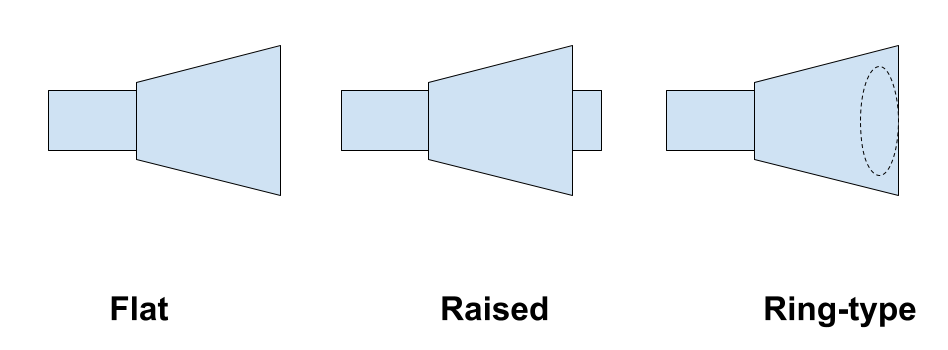
(where P is pressure, F is force, and A is area), a decrease in surface area means a greater pressure for the same fluid force. A smaller flange face must therefore contain a gasket of harder material to withstand the increase in pressure. Flange faces can come in a variety of styles; some of the most common ones are outlined below:
Swagelok flanges meet different regional standards, such as ASME, DIN, and EN, and additional requirements such as API standards are also available.
There are many types of threaded fittings, but some are more susceptible to fugitive emissions than others. Although it is not a universal option, compression fittings are an excellent choice when available to curtail emissions. Where appropriate, compression will offer superior protection against leakage; this property arises from the interaction of the front and back ferrule. When placing the fitting on the tube, the front ferrule seals against the fitting itself, while the back ferrule seals against the tubing, offering an excellent grip of the tube to aid in vibration resistance. A larger surface area of the back ferrule where it contacts the tubing also prevents crimping and puncture.
Fugitive emissions of a refinery are a nuisance on multiple levels. They reduce your plant’s efficiency while posing a threat to your operators at appreciable levels. There are only savings and peace of mind to be gained by reducing fugitive emissions to the lowest possible levels. Beyond those concerns, there are ever-looming regulatory fines and penalties for refineries that are unsuccessful in their attempts to curb emissions as Edmonton and the rest of Canada marches to the goal of a 40-45% reduction of 2012 fugitive emission levels by 2025.
For all the complexities of your fluid system and the value of its uninterrupted uptime, let an Edmonton Valve & Fitting Field Advisor collaborate on your system design to offer top-notch performance and reliability. Combatting fugitive emissions in your facility may seem dizzying, but our experts can provide you with exceptional support and operator training to assist your efforts every step of the way.